Network Home Lab Project
I built this network home lab environment using Cisco Packet Tracer to gain hands-on experience designing, configuring, and verifying multi-subnet enterprise network topologies. Building on my CCNA studies and network fundamentals, this project bridges theoretical concepts—such as the OSI model, L2 switching, L3 inter-subnet routing, and subnet design—with realistic implementation and packet-level verification.
This post walks through the complete lifecycle of the lab: from physical topology planning and Cisco IOS command-line configuration to protocol simulation (analyzing ARP and ICMP packet flow) and advanced subnet allocation using Variable Length Subnet Masking (VLSM).
Lab Environment
- Simulation Platform: Cisco Packet Tracer
- Network Infrastructure:
- Central Gateway: Cisco Modular Router connecting independent broadcast domains.
- Access Switches: Two Cisco Catalyst 2960 Layer 2 switches (
Switch0andSwitch1). - End Systems: Three client workstations (
PC1,PC2,PC3) and one departmental server (Server1).
- Topology Scope: Two distinct Local Area Networks (LAN A and LAN B) interconnected via dedicated router FastEthernet interfaces.
Network Architecture & Addressing Table
The lab divides the network into two primary subnets: LAN A (192.168.10.0/24) representing the local office workstations, and LAN B (192.168.20.0/24) hosting user endpoints and a shared resource server.
| Device | Interface | IP Address | Subnet Mask | Default Gateway | Function / Description |
|---|---|---|---|---|---|
| Router | Fa0/0 | 192.168.10.1 | 255.255.255.0 | N/A | LAN A Default Gateway |
| Router | Fa0/1 | 192.168.20.1 | 255.255.255.0 | N/A | LAN B Default Gateway |
| Switch0 | Fa0/24 | N/A | N/A | N/A | Trunk / Uplink to Router Fa0/0 |
| Switch0 | Fa0/1 | N/A | N/A | N/A | Access port connected to PC1 |
| Switch0 | Fa0/2 | N/A | N/A | N/A | Access port connected to PC2 |
| Switch1 | Fa0/24 | N/A | N/A | N/A | Trunk / Uplink to Router Fa0/1 |
| Switch1 | Fa0/1 | N/A | N/A | N/A | Access port connected to PC3 |
| Switch1 | Fa0/2 | N/A | N/A | N/A | Access port connected to Server1 |
| PC1 | Fa0 | 192.168.10.10 | 255.255.255.0 | 192.168.10.1 | Client Workstation (LAN A) |
| PC2 | Fa0 | 192.168.10.20 | 255.255.255.0 | 192.168.10.1 | Client Workstation (LAN A) |
| PC3 | Fa0 | 192.168.20.10 | 255.255.255.0 | 192.168.20.1 | Client Workstation (LAN B) |
| Server1 | Fa0 | 192.168.20.100 | 255.255.255.0 | 192.168.20.1 | Application Server (LAN B) |
flowchart LR
    subgraph LAN_A ["LAN A (192.168.10.0/24)"]
        PC1["PC1<br/>192.168.10.10"] --- SW0["Switch0<br/>(Catalyst 2960)"]
        PC2["PC2<br/>192.168.10.20"] --- SW0
    end

    SW0 -- "Fa0/24" --- R_Fa0["Fa0/0<br/>192.168.10.1"]

    subgraph Core ["Routing Layer"]
        R_Fa0 --- Router["Cisco Router"] --- R_Fa1["Fa0/1<br/>192.168.20.1"]
    end

    R_Fa1 --- SW1["Switch1<br/>(Catalyst 2960)"]

    subgraph LAN_B ["LAN B (192.168.20.0/24)"]
        SW1 -- "Fa0/1" --- PC3["PC3<br/>192.168.20.10"]
        SW1 -- "Fa0/2" --- SRV1["Server1<br/>192.168.20.100"]
    end
Step-by-Step Walkthrough
Step 1: Topology Design and Physical Cabling
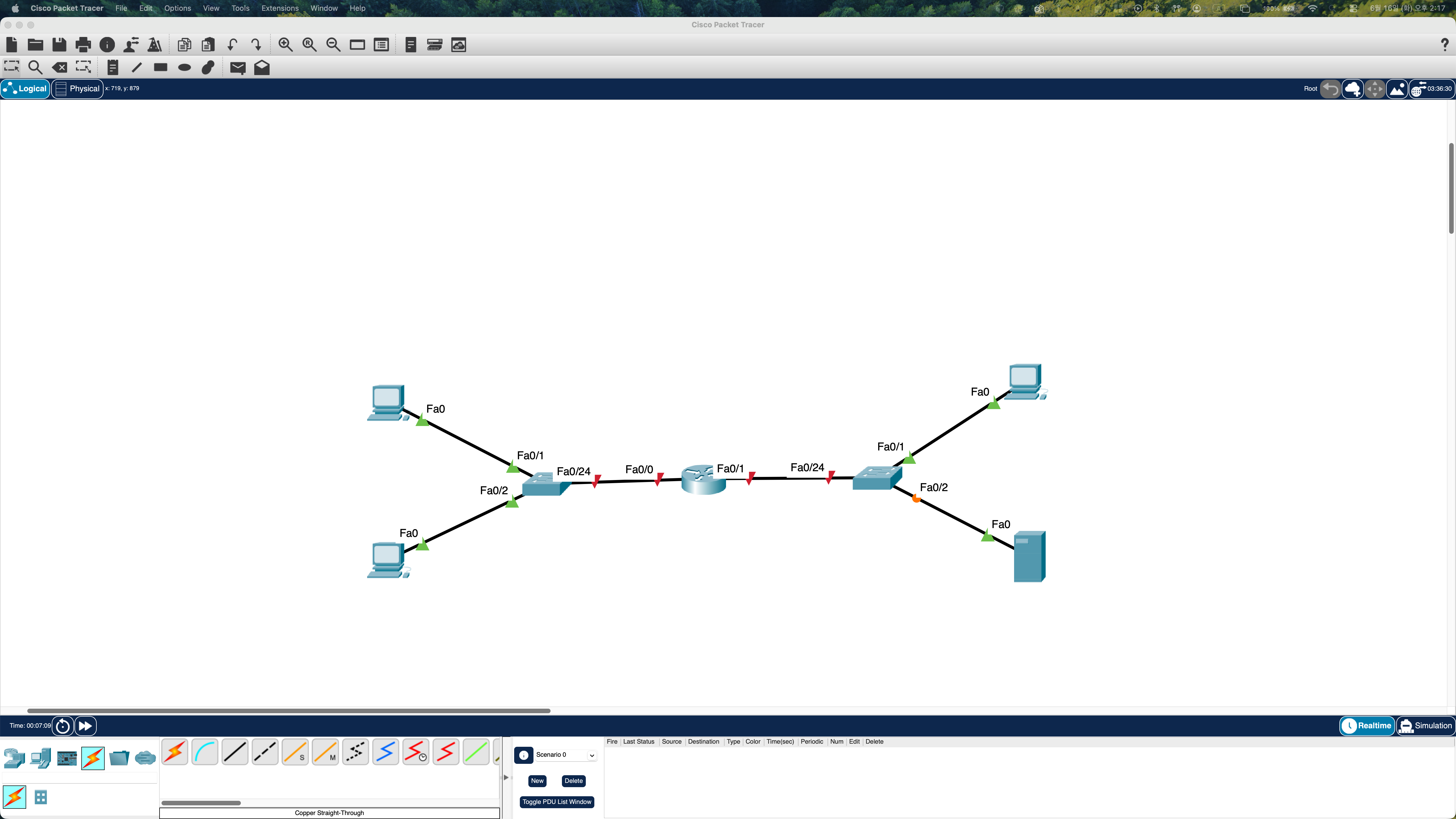
Figure 1: Complete multi-subnet network topology deployed in Cisco Packet Tracer.
The network layout was assembled by placing two Catalyst 2960 switches, a central router, three client PCs, and one server on the workspace:
- Host-to-Switch Connections: Wired using Copper Straight-Through cables from each host’s FastEthernet interface to switch access ports (
Fa0/1,Fa0/2). - Switch-to-Router Uplinks: Connected from port
Fa0/24of each switch to router interfacesFastEthernet 0/0andFastEthernet 0/1. - Link Status Indicators: Initially, the links connected to the router showed red triangles, indicating that router interfaces are administratively shut down by default in Cisco IOS until explicitly brought up.
Step 2: Router Interface Configuration and Activation
To enable communication between the two broadcast domains, each router interface must be assigned an IP address matching its respective subnet gateway and enabled with no shutdown.
1
2
3
4
5
6
7
8
9
10
11
12
13
14
15
16
17
18
19
20
21
22
23
Router> enable
Router# configure terminal
Enter configuration commands, one per line. End with CNTL/Z.

! Configure LAN A Gateway Interface
Router(config)# interface FastEthernet 0/0
Router(config-if)# description Gateway for LAN A (192.168.10.0/24)
Router(config-if)# ip address 192.168.10.1 255.255.255.0
Router(config-if)# no shutdown
Router(config-if)# exit

! Configure LAN B Gateway Interface
Router(config)# interface FastEthernet 0/1
Router(config-if)# description Gateway for LAN B (192.168.20.0/24)
Router(config-if)# ip address 192.168.20.1 255.255.255.0
Router(config-if)# no shutdown
Router(config-if)# exit

Router(config)# end
Router# copy running-config startup-config
Destination filename [startup-config]?
Building configuration...
[OK]
Executing no shutdown transitions the interface state from administratively down to up, bringing both Layer 1 (physical carrier) and Layer 2 (data link line protocol) into an active state. Once the interfaces came up, the link indicators in Packet Tracer turned green.
Step 3: Layer 2 Switch Forwarding Mechanics
Switches forward traffic within the local area network using Layer 2 MAC addresses. As frames enter the switch, it dynamically populates its Content Addressable Memory (CAM) table through three key operations:
- Learning: Inspects the source MAC address of incoming frames and records the associated ingress port into the MAC address table.
- Forwarding / Filtering: Looks up the destination MAC address in the table. If found, the frame is forwarded solely out of the matched physical port.
- Flooding: If the destination MAC address is not yet learned (unknown unicast) or is a broadcast frame (
FF:FF:FF:FF:FF:FF), the switch forwards the frame out of all ports except the receiving port.
1
2
3
4
5
6
7
8
9
10
Switch0# show mac address-table
          Mac Address Table
-------------------------------------------

Vlan    Mac Address       Type        Ports
----    -----------       --------    -----
   1    0001.42a1.1101    DYNAMIC     Fa0/1
   1    0001.42a1.1102    DYNAMIC     Fa0/2
   1    00d0.ba76.5401    DYNAMIC     Fa0/24
Total Mac Addresses for this criterion: 3
This table confirms that Switch0 has mapped PC1 to Fa0/1, PC2 to Fa0/2, and the router gateway to the uplink port Fa0/24.
Step 4: Host Addressing and Default Gateway Assignment
Hosts within each subnet require an IP address, subnet mask, and a default gateway:
- When a host initiates traffic to an IP address within its own subnet (e.g.,
192.168.10.10to192.168.10.20), the bitwise AND calculation between its IP and subnet mask indicates a local destination, and it resolves the target host’s MAC directly via local ARP. - When the destination IP falls outside the local subnet (e.g.,
192.168.10.10attempting to reach192.168.20.100), the host identifies that the packet must leave the broadcast domain and directs the frame to its Default Gateway (192.168.10.1).
If the default gateway is misconfigured or omitted, hosts can communicate with immediate neighbors on the same switch, but all inter-subnet and external traffic will immediately drop.
Step 5: Protocol Simulation and Packet Flow Analysis
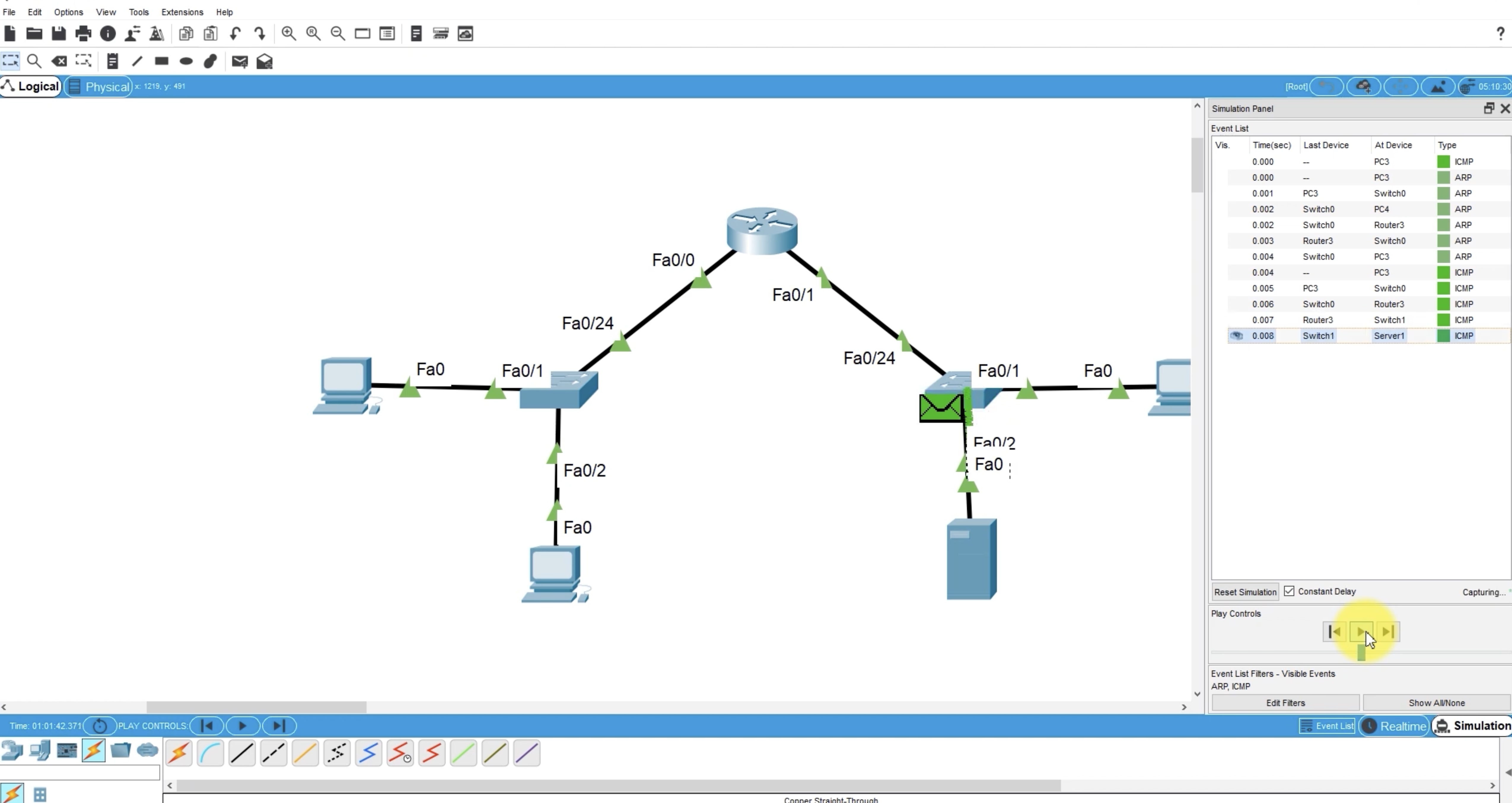
Figure 2: Packet Tracer simulation mode tracing real-time ARP address resolution and ICMP Echo traffic across the router.
Using Packet Tracer’s Simulation Mode, I stepped through the event pipeline for an ICMP Echo packet traversing from LAN A across the router to Server1 in LAN B:
sequenceDiagram
    autonumber
    participant Host as PC (LAN A)
    participant SW0 as Switch0
    participant Router as Central Router
    participant SW1 as Switch1
    participant Server as Server1 (LAN B)

    Note over Host: Ping 192.168.20.100<br/>Target is outside subnet
    Host->>SW0: ARP Request (Broadcast: Who has 192.168.10.1?)
    SW0->>Router: Floods ARP Request
    Router-->>Host: ARP Reply (Unicast: Router Fa0/0 MAC)
    Note over Host: Encapsulates ICMP in L2 Frame<br/>Dst MAC: Router Fa0/0, Dst IP: 192.168.20.100
    Host->>SW0: ICMP Echo Request
    SW0->>Router: Forwards to Fa0/0
    Note over Router: De-encapsulates L2 Frame<br/>L3 Route Lookup: 192.168.20.0 via Fa0/1<br/>Rewrites L2 Header (Dst MAC: Server1)
    Router->>SW1: ICMP Echo Request (via Fa0/1)
    SW1->>Server: Forwards to Server1
    Server-->>SW1: ICMP Echo Reply (Dst IP: 192.168.10.x)
    SW1-->>Router: Forwards Echo Reply to Gateway
    Router-->>Host: Rewrites L2 Header & Delivers Echo Reply
Detailed Hop-by-Hop Breakdown
- Initial ARP Resolution:
- The transmitting host generates an ICMP packet for
192.168.20.100. Because the IP is non-local, the host queries its ARP cache for the default gateway (192.168.10.1). - Finding no entry, the host buffers the ICMP packet and transmits an ARP Request with broadcast destination MAC
FF:FF:FF:FF:FF:FF. Switch0floods the frame. The router receives the request and returns an ARP Reply containing itsFa0/0MAC address.
- The transmitting host generates an ICMP packet for
- L2 Encapsulation for Hop 1:
- The host updates its ARP table and constructs an Ethernet II frame:
Source MAC: Host MAC Destination MAC: Router Fa0/0MACSource IP: 192.168.10.xDestination IP: 192.168.20.100
- The host updates its ARP table and constructs an Ethernet II frame:
- Router De-encapsulation and L3 Routing Decision:
- The router receives the frame on
Fa0/0, validates the destination MAC, strips the Layer 2 header, and examines the Layer 3 destination IP (192.168.20.100). - It performs a routing table lookup (
show ip route) and finds directly connected network192.168.20.0/24on interfaceFastEthernet 0/1.
- The router receives the frame on
- L2 Header Rewriting for Hop 2:
- The router looks up
Server1’s MAC address via ARP on LAN B. - It encapsulates the original IP payload into a brand new Layer 2 frame:
- Source MAC: Router
Fa0/1MAC - Destination MAC:
Server1MAC - Source IP:
192.168.10.x(Unchanged) - Destination IP:
192.168.20.100(Unchanged)
- Source MAC: Router
- The router looks up
Core Architectural Insight: Layer 2 MAC addresses change at every router hop as frames are rebuilt for each physical link, but the end-to-end Layer 3 IP header remains preserved.
Step 6: VLAN Segmentation and 802.1Q Trunking Architecture
In a production environment, physical switches are partitioned into multiple Virtual Local Area Networks (VLANs) to isolate broadcast domains and enhance departmental security:
1
One VLAN = One Broadcast Domain = One Logical Subnet
Port Modes: Access vs. Trunk
- Access Port: Carries untagged traffic dedicated to a single VLAN. Used for endpoints like client PCs and local printers.
- Trunk Port: Multiplexes traffic across multiple VLANs over a single physical cable using IEEE 802.1Q tagging, which inserts a 4-byte tag (including a 12-bit VLAN ID) into the Ethernet frame header.
1
2
3
Switch(config)# interface FastEthernet 0/24
Switch(config-if)# switchport mode trunk
Switch(config-if)# switchport trunk allowed vlan 10,20,99
With 802.1Q trunking, inter-VLAN routing can be accomplished using a Router-on-a-Stick (ROAS) design, creating sub-interfaces on a single physical router port:
1
2
3
4
5
6
7
Router(config)# interface FastEthernet 0/0.10
Router(config-subif)# encapsulation dot1Q 10
Router(config-subif)# ip address 192.168.10.1 255.255.255.0

Router(config)# interface FastEthernet 0/0.20
Router(config-subif)# encapsulation dot1Q 20
Router(config-subif)# ip address 192.168.20.1 255.255.255.0
Step 7: Subnetting and Address Space Design (VLSM)
Subnetting divides large address spaces into right-sized subnets to prevent IP address exhaustion and contain broadcast traffic.
To illustrate realistic address planning, consider an organization allocated a single Class C block (192.168.10.0/24, 256 total addresses) with varying departmental requirements:
- 1st Floor (Sales): Requires 100 hosts
- 2nd Floor (Engineering): Requires 50 hosts
- 3rd Floor (Executive / Server): Requires 30 hosts
Applying Variable Length Subnet Masking (VLSM) allocates the largest requirement first:
- 1st Floor (100 hosts): Requires 7 host bits ($2^7 = 128 \ge 100$). Prefix:
/25(Mask:255.255.255.128). - 2nd Floor (50 hosts): Requires 6 host bits ($2^6 = 64 \ge 50$). Prefix:
/26(Mask:255.255.255.192). - 3rd Floor (30 hosts): Requires 5 host bits ($2^5 = 32 \ge 30$). Prefix:
/27(Mask:255.255.255.224). - Remaining Space: Unallocated
/27block reserved for future expansion or point-to-point router links.
| Area / Subnet | Host Need | Prefix | Subnet Mask | Network Address | Usable Host Range | Broadcast Address |
|---|---|---|---|---|---|---|
| 1st Floor | 100 | /25 | 255.255.255.128 | 192.168.10.0 | 192.168.10.1 - 192.168.10.126 | 192.168.10.127 |
| 2nd Floor | 50 | /26 | 255.255.255.192 | 192.168.10.128 | 192.168.10.129 - 192.168.10.190 | 192.168.10.191 |
| 3rd Floor | 30 | /27 | 255.255.255.224 | 192.168.10.192 | 192.168.10.193 - 192.168.10.222 | 192.168.10.223 |
| Reserved | 30 | /27 | 255.255.255.224 | 192.168.10.224 | 192.168.10.225 - 192.168.10.254 | 192.168.10.255 |
flowchart TD
    Base["192.168.10.0/24<br/>(256 Total Addresses)"]
    Base --> Sub1["1st Floor: 192.168.10.0/25<br/>(Addresses 0 - 127 | 126 Usable Hosts)"]
    Base --> Rem1["Remaining: 192.168.10.128/25"]
    Rem1 --> Sub2["2nd Floor: 192.168.10.128/26<br/>(Addresses 128 - 191 | 62 Usable Hosts)"]
    Rem1 --> Rem2["Remaining: 192.168.10.192/26"]
    Rem2 --> Sub3["3rd Floor: 192.168.10.192/27<br/>(Addresses 192 - 223 | 30 Usable Hosts)"]
    Rem2 --> Sub4["Reserved: 192.168.10.224/27<br/>(Addresses 224 - 255 | 30 Usable Hosts)"]
Step 8: Network Verification and Diagnostics
Once all configurations were applied, I ran diagnostic verification commands on the router and hosts to validate route convergence and link health.
Checking Router Interface Status
1
2
3
4
Router# show ip interface brief
Interface              IP-Address      OK? Method Status                Protocol
FastEthernet0/0        192.168.10.1    YES manual up                    up
FastEthernet0/1        192.168.20.1    YES manual up                    up
Both interfaces report Status: up (Layer 1 physical link operational) and Protocol: up (Layer 2 data link framing active).
Inspecting the Kernel Routing Table
1
2
3
4
5
6
7
8
Router# show ip route
Codes: C - connected, S - static, R - RIP, M - mobile, B - BGP
       D - EIGRP, EX - EIGRP external, O - OSPF, IA - OSPF inter area

Gateway of last resort is not set

C    192.168.10.0/24 is directly connected, FastEthernet0/0
C    192.168.20.0/24 is directly connected, FastEthernet0/1
The router displays both subnets as directly connected (C), confirming routes exist to switch packets between 192.168.10.0/24 and 192.168.20.0/24.
End-to-End Ping Verification
From PC1 (192.168.10.10), tested end-to-end connectivity to Server1 (192.168.20.100):
1
2
3
4
5
6
7
8
9
10
11
12
13
PC> ping 192.168.20.100

Pinging 192.168.20.100 with 32 bytes of data:

Reply from 192.168.20.100: bytes=32 time=12ms TTL=127
Reply from 192.168.20.100: bytes=32 time=9ms TTL=127
Reply from 192.168.20.100: bytes=32 time=8ms TTL=127
Reply from 192.168.20.100: bytes=32 time=8ms TTL=127

Ping statistics for 192.168.20.100:
    Packets: Sent = 4, Received = 4, Lost = 0 (0% loss),
Approximate round trip times in milli-seconds:
    Minimum = 8ms, Maximum = 12ms, Average = 9ms
Zero packet loss confirmed that switching, routing, ARP resolution, and default gateways are functioning properly.
Key Takeaways
- L2 vs. L3 Addressing Roles: Layer 2 MAC addresses are hop-by-hop physical identifiers rewritten at every routing boundary, whereas Layer 3 IP addresses represent the persistent end-to-end logical path.
- Default Gateway Significance: A host relies entirely on its default gateway when communicating outside its local prefix. Without it, inter-subnet routing fails even if the physical links are healthy.
- Packet Simulation Clarity: Using Packet Tracer’s simulation mode provides concrete visibility into the initial ARP broadcast delay (often causing the first ping packet to time out) and subsequent ICMP forwarding.
- Structured VLSM Planning: Designing subnets by allocating the largest host blocks first ensures zero address waste and clean binary boundaries for routing table summarization.